What Does It Take for a Control System to Run Shor’s Algorithm on an Error-corrected Quantum Machine?
Factorizing large numbers is possibly the most sought-after application of quantum computers, for the potential of compromising privacy and security, breaking the RSA encryption that keeps our data and conversations safe from eavesdropping.
Quantum computers have already been used to prove this concept, from the very first demonstration of factoring the number 15 [1], to 143 a decade later [2], and integers up to 48 bits (that is 15 digits!) another decade after that [3]. Although progress has been incredible on noisy intermediate-scale quantum (NISQ) devices, there is a consensus that practical applications will require a fault-tolerant operation achieved by building quantum-error-corrected (QEC) machines. So, we ask: what does it take to run Shor’s algorithm on a quantum device where errors are corrected?
The short answer: a lot. It takes a lot.
We will now explore a seemingly simple example that, surprisingly, leads us to qubit counts and technological hurdles that are currently beyond reach. We’ll look at the factorization of the number 21—a calculation that anyone can do in their head almost instantly, and devise what it would take to do it fault tolerantly. By examining the challenges and requirements involved in solving such a basic problem, we hope to shed light on the current trajectory of quantum control systems and the path we must take to develop the advanced technology at the scale that is needed for quantum error correction.
We will go through the basics here, but feel free to dive deeper with this recording of our CEO Itamar Sivan explaining how impactful control systems are in such protocols.
From a logical circuit to running things on a real device
To factorize the number 21, we only need 5 perfect qubits, and to be able to perform the logical circuit depicted in Figure 1: a bunch of 1-, 2- and 3-qubits non-Clifford gates. The problem is that qubits are not perfect. They are highly fragile analog beasts, and we need to work hard to actively keep errors from destroying the quantum information and computation we do with them.

Figure 1: logical circuit to factorize the number 21.
The first step, for the sake of concreteness, is choosing which qubit technology we are going to consider: superconducting for this example. Second, we need to choose a QEC scheme that we can implement. Here we went with surface codes, the most widely used scheme with superconducting quantum processing units (QPUs).
Realizing logical qubits using surface implementation imposes constraints that inevitably change the circuit, both in terms of the number of qubits, by adding many ancillas, and in terms of operations [5]. For example, surface codes do not allow for direct T and S gates (see Figure 2), and even a CNOT looks quite a bit different once we include QEC stabilizers.

Figure 2: T-gate conversion into surface codes requires decoding-dependent feed-forward operations and magic-state initializations.
Once we consider the full circuit implementation within the boundaries of a surface code, we end up needing 1015 physical qubits (assuming physical error rates of 0.1% per gate), 400 fault-tolerant surface-level gates and 14 magic-state initializations with 99.7 % fidelity. That’s just to factorize the number 21.
Putting aside for a moment the fact that we need to manufacture a chip with 1015 superconducting qubits showing exquisite error rates, we will focus on what this all means for the control system that must handle such a protocol. We will discuss the requirements and what Quantum Machines (QM) is doing about it, focusing on 4 categories: Scale, analog specs, real-time classical processing and ease-of-use.
Quantum control at scale
Controlling 1015 qubits requires thousands of synchronized analog control channels attached to a powerful orchestration brain able to handle thousands of simultaneous operations. Adopting a modular approach, QM has tackled this challenge by creating OPX1000, the most advanced and highest-scale quantum controller in industry.
The OPX1000 was designed with scalable real-time data sharing and clock distribution in mind – we will see how important the clock is for e.g., keeping phase stable. OPX1000 offers the highest density of channels, 26.7 per rack unit size, and allows scalability both in hardware and software, with identical programming of 1 or N units. This is not a given. It requires a clever hardware architecture, dedicated components and expertise to reach such scalability levels, and we will see some of these choices, so read ahead.

Figure 3: OPX1000 allows to power over 1000 superconducting qubits thanks to its scalable architecture, highest-in-industry channel density and proprietary tech.
Analog specs as a necessary evil
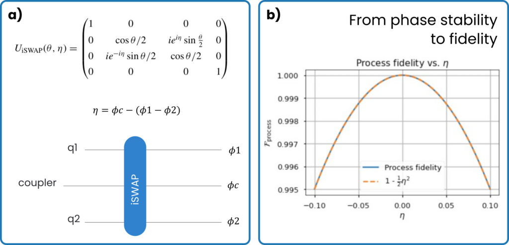
A basic assumption of the QEC model we discuss is that gate errors should be < 0.1 %. If this was not the case, then the QEC rounds would not run fast enough to correct all errors. From this assumption, many hidden requirements are derived. Let’s focus on a very important one: phase stability. If we take two pulses aimed at two different qubits for e.g., an iSWAP gate, then we really need the phase of the pulses to be the same. In fact, the gate fidelity will quickly decrease if the phase is not the same, and to remain below 0.1 % error, says our model, we need phase difference to be less than 14 mrad (see Figure 4).
But why would the phase be different if we send the same signal? In experiments nothing is ever exactly the same, so it boils down to components, temperature variations, distance and every tiny detail. For example, if you built your controller with phase-locked loops (PLLs, a standard component for controllers) to keep phase constant, then good luck. They are not good enough for this (check out our DDS blog to read more). The entire architecture of the controller and its hierarchy needs to be designed with those most stringent requirements in mind.

Figure 4: How the phase difference between two signals impacts iSWAP fidelity.
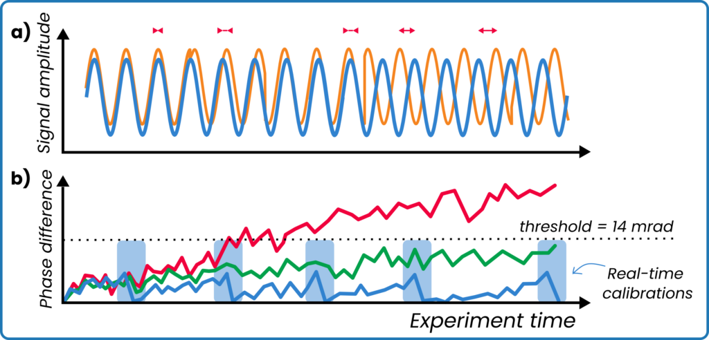
Phase is noisy and drifty (see cartoon in Figure 5), but fortunately the OPX1000 has been designed to keep disturbances to a minimum, allowing for less than 5mrad of RMS jitter and less than 6mrad of phase drift in 1 hour (ask us for a full spec-sheet). Additionally, the ability to perform active real-time re–calibrations of parameters – which is a necessity for QEC – is used to reduce phase differences even further.

Figure 5: a) Sketch depicting accumulating phase difference between two signals; b) Phase drift and noise for different systems: generic controller (red line), OPX1000 with active real-time calibration turned off (green line), OPX1000 with active real-time calibration turned on and taking place within the light-blue areas (blue line).
Classical compute for advanced control and decoding
Such real-time calibration of parameters is a small part of a large class of capabilities of performing classical computation within the time frame of quantum sequences. This integration of classical computing within quantum coherence is a key necessary component that too often gets overlooked. Without classical decoding, there is no quantum error correction.

Figure 6: Operations are performed both offline and during runtime. The controller maps measurements with decoding tasks, orchestrates pulses and feed-forward operations gives the decoders’ response. Multiple decoders run in parallel to handle the layers of decoding present in any implementation of QEC.
Our models substantiate the key role of that latency plays in enabling QEC [5]. The controller maps measurements and handle decoding data (in and out of decoders), on top of orchestrating the dynamic sequence, including feed-forward operations (see Figure 6). But all of this is not useful if the QPU-controller latency is higher than a few hundreds of nanoseconds. Fortunately, QM’s Pulse Processing Unit (PPU) proprietary technology powering the OPX allows to keep this latency low, while offering a complete classical compute capability.
On the decoder side, we will likely need several decoders running in parallel and the QPU-decoder latency cannot exceed 10 µs, otherwise the QEC scheme will not lead to a stable system, latencies will diverge, and we would lose track of errors. Because of this, QM has partnered with NVIDIA to create DGX Quantum, a revolutionary product promising < 4 µs round-trip latency for data path between the controller and the GPU server, via real-time communication between an OPX and a Grace Hopper installed at the same location. This will be the first ever real-time integration of CPU, GPU and QPU.
Easy and flexible programming
Given a system such as the one in Figure 6, implementing a 1015-qubits circuit with 1-4000 control channels and several parallel decoders running on CPU/GPUs, there is one truth very clear to the experimentalist. This is not going to work if programming is not easy and flexible enough. It’s not only complicated sequences to write. It is also sequences that are expected to change frequently, as new decoding schemes are proposed, better control sequences discovered, and development pushes forward. This is one of the reasons controllers are still mostly built on FPGA and not ASIC, as FPGAs are re-programmable. With OPX controllers, QM continuously releases new firmware that introduces new capabilities as quantum technology develops and its needs are changing.
The OPX’s PPU and its pulse programming language QUA enable fast and easy programming of pulse sequences, while being fully integrated with both CUDA for decoder programming on GPUs and higher-level software, such as QBridge for HPC SLURM schedular integration and OpenQASM3 for gate level coding (Cirq, Qiskit). Integration is a big part of success for quantum controllers, but the programming that comes from integration has to be simple, effective and flexible.
Requirements and benchmarks for quantum controllers
This was just a basic overview of what comes out when considering quantum error correction for useful applications. To dive deeper in the subject feel free to read our recent work in literature [4–5], and check our feedback page and our benchmarking page. In the meantime, I leave you with a representation of the operations necessary for a smaller version (d=3) of the d=5 surface code we simulated for this work, showing the hundreds of thousands of gates needed to factorize the number 21. SPOILER: The answer is indeed 3*7.

Figure 7: Animation of part of a d=3 surface code for factorizing the number 21.
References
[1] Vandersypen, Lieven MK, et al. “Experimental realization of Shor’s quantum factoring algorithm using nuclear magnetic resonance.” Nature 414.6866 (2001): 883-887.
[2] Xu, Nanyang, et al. “Quantum factorization of 143 on a dipolar-coupling nuclear magnetic resonance system.” Physical review letters 108.13 (2012): 130501.
[3] Yan, Bao, et al. “Factoring integers with sublinear resources on a superconducting quantum processor.” arXiv preprint arXiv:2212.12372 (2022).
[4] Ella, Lior, et al. “Quantum-classical processing and benchmarking at the pulse-level.” arXiv preprint arXiv:2303.03816 (2023).
[5] Kurman, Yaniv, et al. “Control Requirements and Benchmarks for Quantum Error Correction.” arXiv preprint arXiv:2311.07121 (2023).
